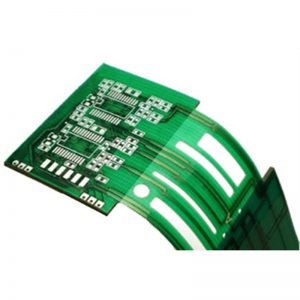
Maximum Bending Radius For Rigid Flex Circuits
Bending Radius For Rigid Flex Circuits
Rigid flex circuits are a valuable addition to a printed circuit board (PCB) design. By combining rigid parts and flex substrates, they provide both strength and dynamic adaptability to meet the demands of many unique applications. However, this versatility also comes with the challenge of ensuring that these components can endure a wide range of mechanical stresses. This is particularly important when the PCB needs to be bent or flexed repeatedly over the lifetime of the product. In order to avoid premature failure and other issues, it is critical that a proper bending radius is specified and adhered to during the design process.
The bending radius of a rigid flex circuits depends on a variety of factors, including the materials used for both the rigid and flex portions of the design. In particular, different materials have varying thermal expansion coefficients and therefore can impact signal integrity and electromagnetic interference (EMI).

Additionally, choosing the right copper weight for the flex portion of the design is also important as this will directly influence how easily the flex can be bent and rebent. Finally, the choice of which connections are placed at the transition between the rigid and flexible sections is a key factor as well. Poorly placed connectors can lead to increased stress on the flex section and cause damage to the PCB.
Maximum Bending Radius For Rigid Flex Circuits
Understanding the proper bending radius for a flex PCB is essential to the longevity of the product. When a flex PCB is bent too frequently, it can strain the copper and cause traces to tear or become disconnected from the circuitry. This can significantly decrease the overall life of a flex PCB.
To maximize the lifespan of a flex PCB it is recommended that conductors be located inside the neutral bend axis. This will reduce the amount of tensile and compressive shear forces on the conductor during bending. In addition, the conductors should be plated with either panel plated or button plated copper. These plating methods will minimize the amount of copper on the conductor and increase the flexibility of the design.
Another factor that impacts the bending radius of a flex circuit is its overall thickness. A thicker board tends to require a larger bending radius as the flex layers will bunch up at the surface layer when bending.
In general, it is recommended that a flex PCB be designed for dynamic bending (frequent flexing) rather than static bending (no flexing). A rigid-flex circuit should have the correct bending radius specified during the design stage and should be validated using advanced simulation tools and thorough testing before going into production. Failure to follow the recommended bending radii can result in long term reliability and quality concerns as well as expensive product repairs. Therefore, it is crucial that you work with an experienced manufacturer who can help you achieve the best results in your flex or rigid-flex design.