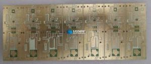
How to Achieve Balanced Transmission Lines in RF PCBs
Achieve Balanced Transmission Lines in RF PCBs
Achieving balanced transmission lines in RF PCBs is essential for efficient signal transfer and low-loss performance. A transmission line consists of two conductors with a specific characteristic impedance and surrounded by an insulating dielectric material to prevent interference and reflections from occurring. Impedance mismatch at each end of a transmission line can cause significant signal distortion, which is observed as signal oscillations on an oscilloscope image.
To achieve high-performance RF circuits, it’s necessary to understand and use impedance matching techniques, such as matched impedance. This process involves adjusting the characteristics of each copper trace and component to match their reflected impedance, thus reducing losses and ensuring proper power transfer. It also helps eliminate noise that can affect the performance of a circuit.
Inductance is another important factor to consider when designing an rf pcb. The more inductance a PCB has, the more it will degrade signal strength and stability. To minimize inductance, you should try to keep the distance between RF signals as short as possible and ensure that each signal has an independent ground reference. You can do this by routing signal lines on separate layers and using multiple via holes to avoid discontinuities in the ground plane. It is also a good idea to make the ground planes as wide as possible and to avoid any gaps or discontinuities in their design.

How to Achieve Balanced Transmission Lines in RF PCBs
RF PCBs often contain several different types of components and transmission lines, so it’s essential to carefully plan the layout of each layer to reduce interference and loss. The traces, signal lines, and ground planes of an RF PCB should be arranged in the order of highest frequency to lowest frequency, as this will minimize signal crosstalk between adjacent layers. It is also a good idea to separate digital signals from RF signals to avoid coupling between them, as these can affect signal stability and performance.
When it comes to the placement of decoupling capacitors, a star configuration is ideal. This configuration centralizes all decoupling capacitors in a single point on the board and connects each of them to the power supply pin through a separate trace, which helps reduce ground loops and noise. It is also important to select capacitors with a self-resonant frequency close to the noise frequency to ensure optimal decoupling.
Another important consideration when laying out RF PCBs is the bend radius of transmission lines. A general rule of thumb is to create an arc with a radius of at least three times the width of the transmission line to minimize the change in characteristic impedance as it moves through the curve. This can be difficult to do on a small PCB, so you may need to use a larger-than-normal component size to achieve the desired layout.
It’s also important to use the correct fabrication technique when creating an RF PCB. For example, the outer laminate layers of an FR-4 PCB typically have a lower glass content than the core, which can impact the circuit’s dielectric constant. In addition, the outer laminated layers of an RF PCB must be properly bonded to the core to ensure that the entire board is electrically conductive.